


flow field test vehicle
2021/2022 -
Purpose
As the mechanical designer of the air cathode assembly, I am responsible for designing the flow field: the flow path geometry that distributes air uniformly across the entirety of our meter tall electrode area.
The flow field itself is protected IP, but the test vehicle I designed in order to evaluate flow field performance was also an iterative process that speaks to my work here.
design elements
-
Acrylic solvent welded vessel
-
Injection molded plastic passthroughs for sensor wire
-
Modular sensor data collection
-
Reusable test vehicle
-
the only part that gets swapped is the flow field assembly
-
-
Can run multiple flow fields at once
design narrative
To design an air flow field, before I do any real-world prototyping, I work with an external consultant to run CFD (computational fluid dynamics) simulations to quickly iterate on geometry without needing to build anything. I'll draw a rough draft in Solidworks Flow Simulation, and then work with a consultant who has expertise in ANSYS to determine a higher fidelity map of expected flow. I iterate in this way until a flow field looks good on paper, and needs to be validated electrochemically.
The impetus for this design project was developing this way to validate these simulation results in practice.
Design #1
The first design I built was a sandwich of clear acrylic with the flow field inside that I could run a set volume flow rate through with resealable holes through which one could stick incense through to visualize smoke flow velocity and directionality. I measured velocity through an app called Tracker, which takes video input, a user-inputted distance measurement and markers per frame to calculate velocity. A video of this process is shown below:
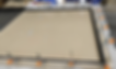
Acrylic fixture with air gap in between for flow field
Video showing smoke tracking software
This design had a few flaws. It was difficult to maintain a perfect seal around the perimeter and the smoke tracking had to be done manually, which was a tedious process. We also decided that ultimately, the thing we were trying to measure was cathode performance, and after consulting with various subject matter experts at Form, learned that the effects of the rest of the cell chemistry would be significant enough that any cathode performance would need to be measured in an electrochemical cell.
Design #2
In this design, I made an acrylic vessel to contain the cell chemistry, a sensor wire array sealed in epoxy with 15 measurement points, and tried to make a modular assembly where the only thing that would need to get swapped out between tests was the flow field subassembly. This fixture made a celebrity cameo in this NPR article.
.jpg)

Each of the white squares in the assembly I'm pushing is a sensor measurement point
Hooking up air line connections to the cell
This design also had a few flaws. I tried to protect the copper busbars with an epoxy and had issues mid-test with corrosion from the electrolyte reaching the copper, which skewed the data. I also constructed the vessel myself, and had to repair a couple pinhole leaks due to not sufficiently polishing the edges of the acrylic before welding it together. It was also difficult to get the full picture of the flow field due to the sparse spacing of sensor wires, and unwieldy to swap out the flow field assembly because of the height you had to lift it.
Design #3
This design is in progress now, but I've made a lot of improvements. One constraint I ran into in the previous design is that it was difficult to get testing real estate on our limited full cell test stands - the infrastructure that cycles the cells and collects data. I wanted to maximize space in this design to make it possible to test multiple flow fields at a time for faster iterations. Some details are redacted - the flow field assembly is pictured as a black box.


Concept sketches I reviewed with the team prior to CAD

Hook for safe lifting via gantry
Clamps to seal against the lid
Lifting flow field assembly

Lid with O-ring groove
Flow field assembly creates a face-seal

Full Assembly view
200 measurement points (front and back)


Evil Avocados
(Ensuring vessel does not fail against
electrolyte hydrostatic pressure)
Ensuring lid does not fail due to clamp force required to maintain O-ring compression seal
sensor wall assembly

Sensor wires are placed in the blue injection-molded parts that are solvent welded to the clear acrylic plate
Epoxy gets poured into each well

After the epoxy is cured, the plate is inverted, and the caps are cut off to reveal the sensor wire

Side view - the exposed circle of wire
is inside the electrolyte

The backside of each wire gets connected to a
lever nut connector that can be routed
to the data acquisition system
I'll be building this design through the end of the year and using it to collect a more granular picture of how our flow fields perform.
conclusions & Acknowledgements
This project has not yet concluded, but I am hopeful this last iteration will be a dependable and re-usable test vehicle that can enable quicker design cycles on flow field testing.
All of my work is cross-functional and informed by the expertise of many people. Thanks to Angel, Joe, Nick, and Kathy for being my ME mentors and thanks to Meghan, Danielle, and Vlad of the cathode team for schooling me in science.